


For detailed information, other images and documents, please select individual articles from the following table.


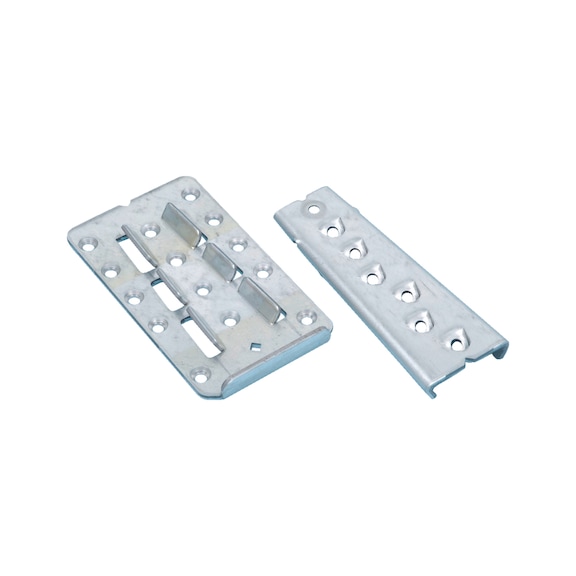
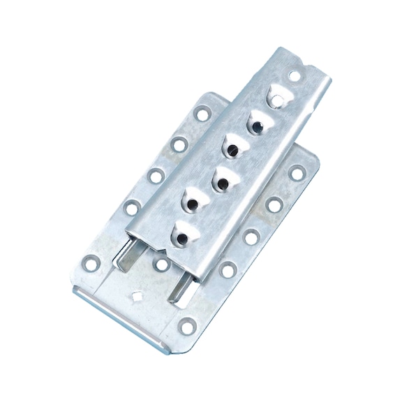
Concealed beam connector
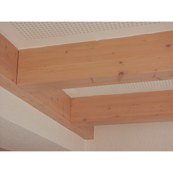
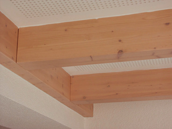
This innovative concealed beam connector with high load-bearing capacity and low installation depth is ideal for concealed wood/wood connections (visible areas) of secondary beams to main beams or posts

Register now and access more than 125,000 products

Variants
- Sloping connections can be constructed at angles of 15° to 165° and gradients of 0° to 55°. Screw into grain-cut timber at an angle of 35° using ASSY 5 x 80 mm countersunk-head, full-thread screws. The screw-in angle is determined by the sheet metal guide.
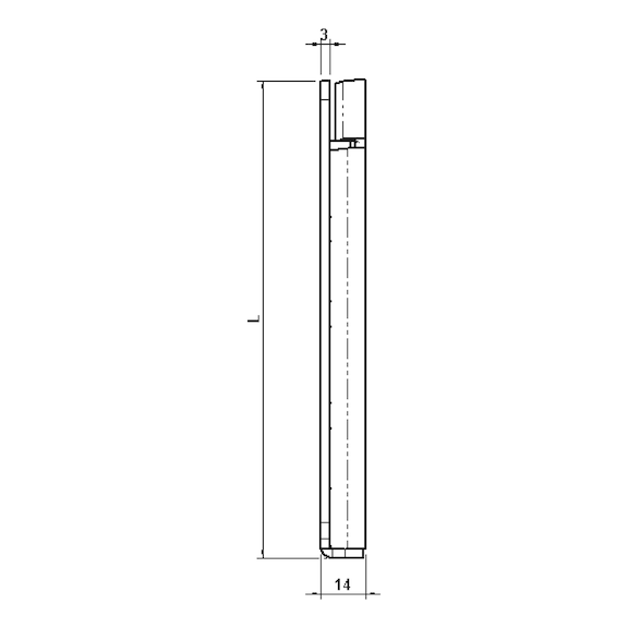
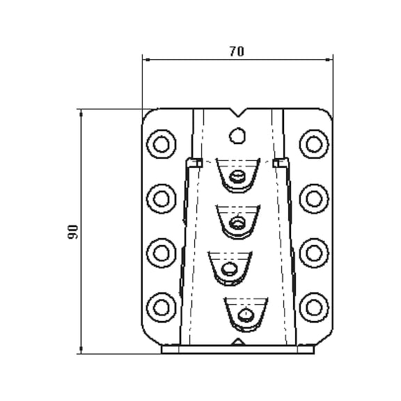
- High load-bearing capacity coupled with low installation depth (14 mm)
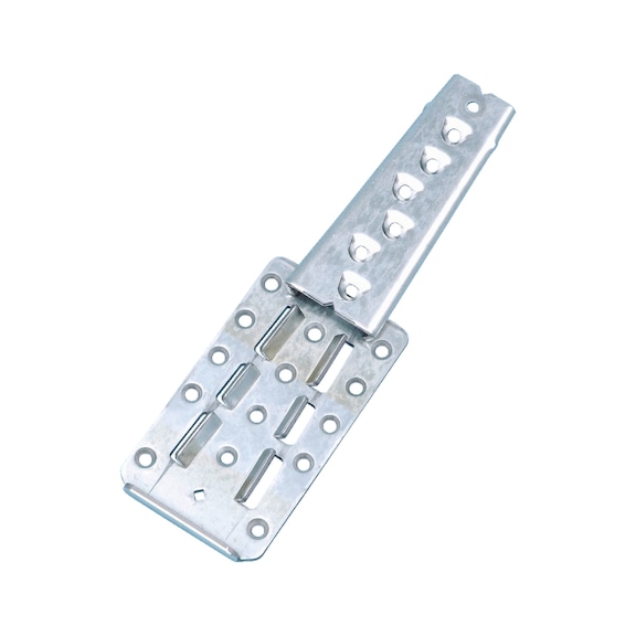
- Conical, swallow tail-style geometry for self-centring and gap-free contact pressure
- High level of possible pre-fabrication in the workshop and easy and quick on-site installation
- Sheet metal hot-dip zinc-plated on both sides (S250GD + Z275 [approx. 20 µm]), thickness 3.0 mm in line with EN 10346:2009
- Application in utilisation class 1 and 2 in line with EN 1995:2013
ETA-09/0301
It is advisable to use the corresponding milling template set for easy and quick pre-assembly.
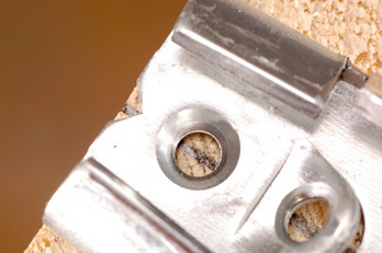
Screw into grain-cut timber at an angle of 35°. The screw angle is determined by the shape of the tabs.
The main beam's transverse strength must be verified separately. If necessary, the joint should be made using ASSY plus VG full-thread screws. For loads perpendicular to the secondary beam axis, the transverse strength must also be verified for the secondary beam. If the main beam is subject to torsion, it must be secured against twisting.
Available work documents:
Load tables and detailed processing instructions can be found on the service page www.wuerth.de/holzverbinder.
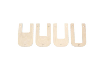 Select a template insert
 Attach template: The fixing holes are used to attach the template to the beam.
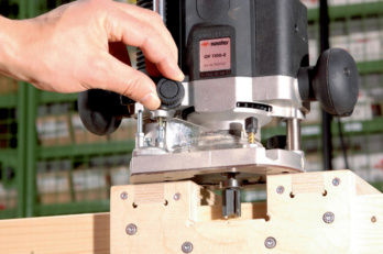 Set the trimming depth of 14 mm
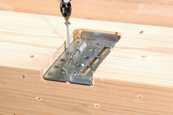
 Mill the recess
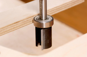 The upper thrust ring enables a simple and fast milling process without damaging the template.
 Mark center of secondary beam.
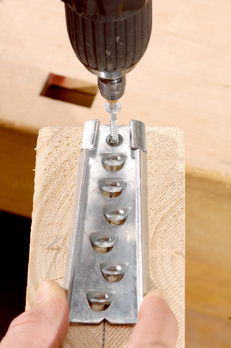 Place the swallow tail-shaped part of the connector centrally on the previously marked secondary beam and screw in the centring screw first of all. The connector must be mounted flush with the upper edge
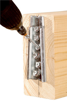 Then screw in the remaining screws at a 35° angle.
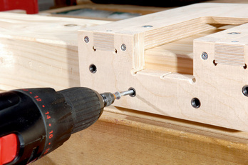
 Fit the connector
into the prepared recess
in the main beam and
screw in the screws.
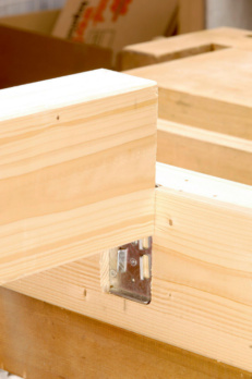 Hook the secondary beam into main beam from above
 Simple mounting thanks tocentering aid.
ETA-09/0301
Load-bearing connections of timber joists to timber main beams or posts in visible areas
Approved fasteners:
ASSY 3.0 countersunk head screw with full thread 5 x 80 to 120 mm (lg ≥ 72 mm) in line with ETA 11/0190 mm
Installation guide:
- Select the template insert
- Place the swallow tail-shaped part of the connector centrally on the previously marked secondary beam and screw in the centring screw first of all. Mount the connector flush with the upper edge
- Screw in the remaining ASSY screws at an angle of 35°
- Fit the connector in the prepared recess of the main beam and screw in the screws
- Fit the secondary beam into main beam from above
Select RAL-colour code
!! NOTE: On-screen visualisation of the colour differs from real colour shade!!