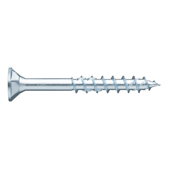


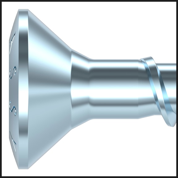


ASSY® 4 CSMP universal screw Steel zinc plated partial thread countersunk milling pocket head
ASSY 4 CSMP steel zinc ptd. PT cs mill. pocket RW
SCR-CSMP-WO-RW40-(A3K)-6X200/70
ASSY 4 CSMP
price per selected packing unit | Individual prices for customers after login


Register now and access more than 125,000 products
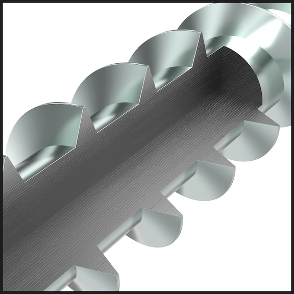
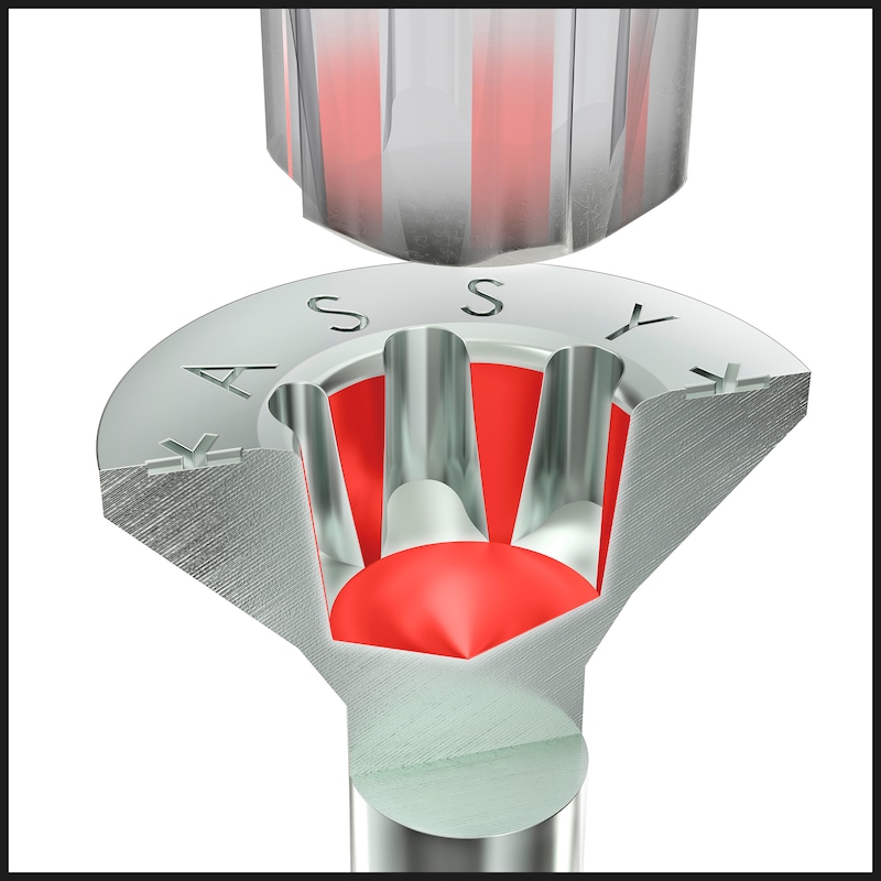
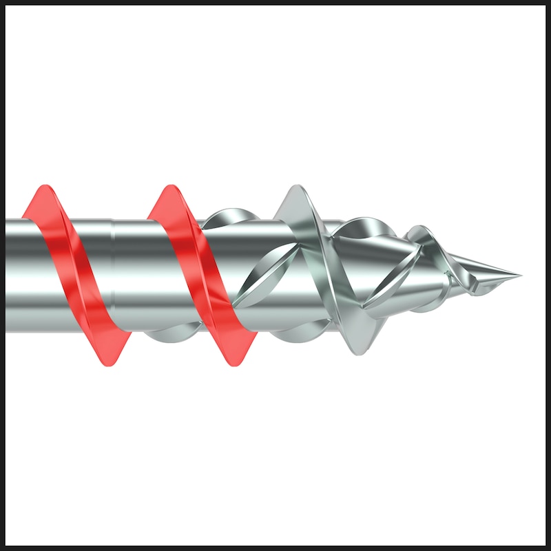
Ideal power transmission thanks to RW recess
- More power due to larger contact area at the bit
- More stability, one-handed working, precise positioning due to the tight-fit recess and perfect fit of the bit
- Fewer bit changes, 1 bit for many screw diameters
- Compatibility with previous AW drive
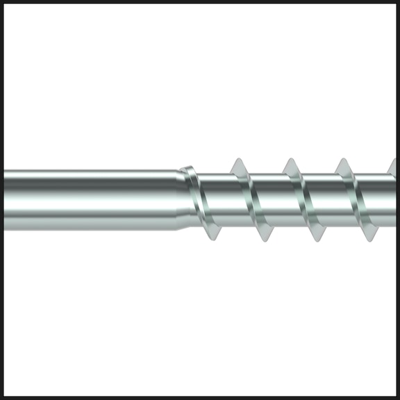
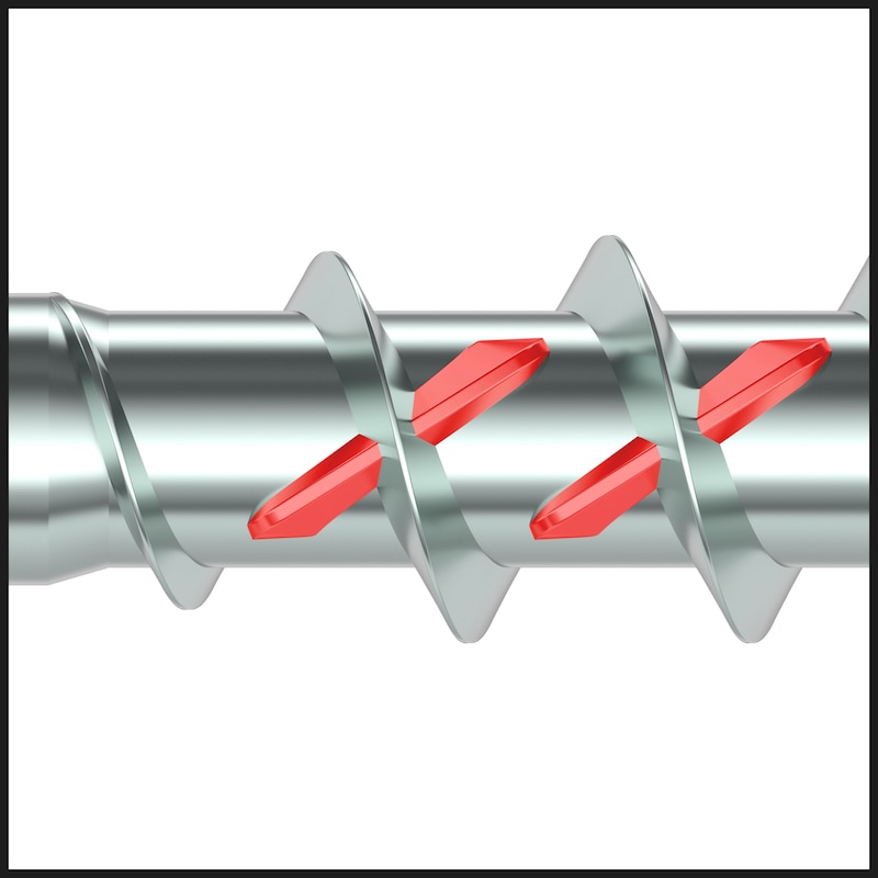
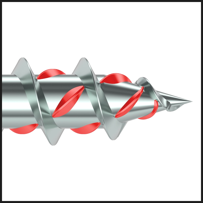
Significant reduction in the amount of force required when screwing in the screw
- Low gap effect when immersing the shank due to the displacement milling effect of the milling shank
- Minimised risk of screw breakage due to high breaking torque
- Reduced risk of injury from protruding metal chips due to the integration of the milling shank into the thread
- High protection of the application tools
No over-tightening or stripping and high feed
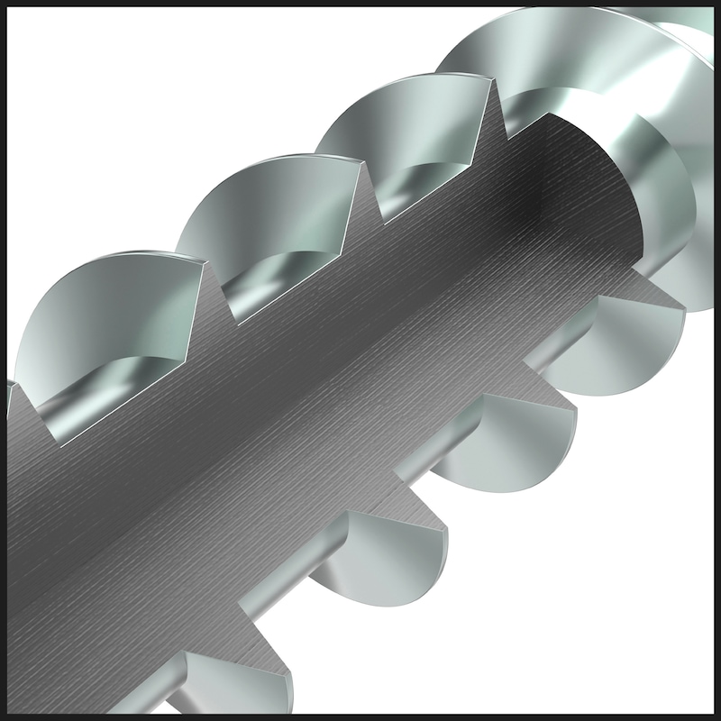
- Higher power transmission in hardwoods due to reinforced, asymmetrical thread flank geometry of the coarse thread
- Better anchorage thanks to higher thread flanks
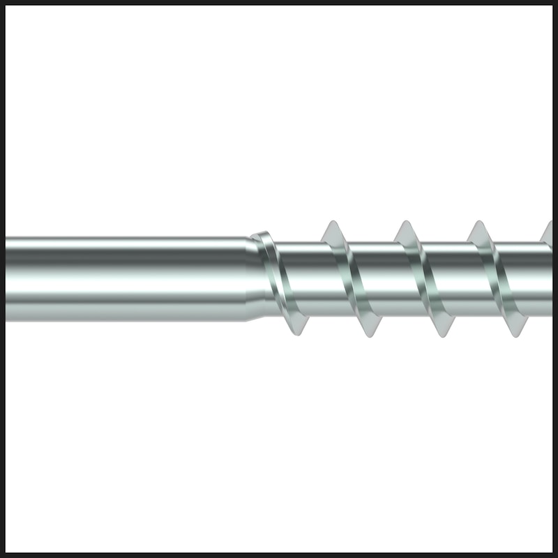
Smooth thread start ensures optimised recessing and biting of the screw
- Low gap effect due to displacement effect of the dome-shaped milling elements in the tip
- Friction-reduced thread rotation allows reduction of the screw-in force to be applied
High strength values and ductility
- Adjusted heat treatment guarantees high strength values and high ductility
ETA-11/0190 approved
- We recommend using the Würth software or the corresponding design aids for planning and dimensioning your assembly. Use the Würth timber construction software for dimensioning of ASSY screws from a diameter of 5 mm
- Do not use the screw in applications with direct exposure to the elements or in humid rooms with atmospheres containing chlorine gas. If used outdoors and in rooms that are constantly exposed to high humidity, please use ASSY 4 A2 or A4 stainless steel screws and, if atmosphere contains chlorine, HCR stainless steel screws
- ASSY 4, ASSYplus 4 and ASSYplus 4 FT chipboard screws are optimised for use in wood and wood materials. For applications in plastic anchors where load capacity can also be reduced, use only screws without an optimised thread tip (tip with milling ribs, drill tip, self-clearing groove etc.), such as the ASSY D screws with countersunk head or pan head
ETA-11/0190 approved
The requirements of the European Technical Approval (ETA) must be observed
Datasheets(X)

Parallel drive size RW30 is available for window applications with a diameter of 6 mm. This makes it easier to combine with AMO screws equipped with RW30.
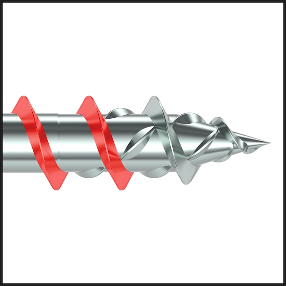
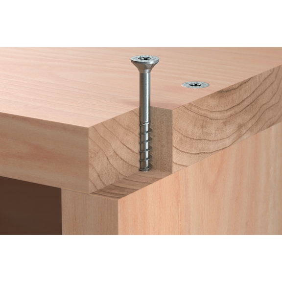
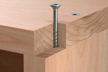
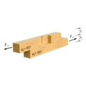
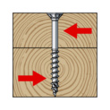
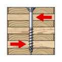
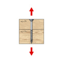
For wood-to-wood connections designed for contraction
The partial thread starting immediately below the shank allows for wood-to-wood connections designed for contraction. In this case the thread is positioned entirely in the lower second component.
For applications in utilisation classes 1 and 2 (from dia. > 4 mm)
- High-quality surface protection zinc blue passivated chromium(VI)-free, up to dia. 4 mm A2K 5 µm, from dia. 4.5 mm A3K 8 µm layer thickness
- Suitable for use in utilisation class 1 (indoor areas) and from dia. > 4 mm in utilisation class 2 (wet areas or covered outdoor areas) in accordance with EN 1995-1-1:2010-12 + DIN SPEC 1052-100:2013-08
- For screws from dia. 4.5 mm with zinc layer thickness 8 µm with Cr(III) passivation, the requirement of classification T2/C2 is fulfilled in accordance with prEN 14592:2017 (D)
- To increase the joining effect or head pull-through resistance, combining with perfectly fitting washers for ASSY 4 is recommended
- ASSY screws are approved for quasi-static loads
- For optimum use of the screw, the right-size RW bit must be used
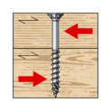
- Partial-thread screws are ideal for connecting wooden components. To achieve optimum assembly of the components, the components to be fixed must not be thicker than the length of the shank
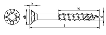 | |
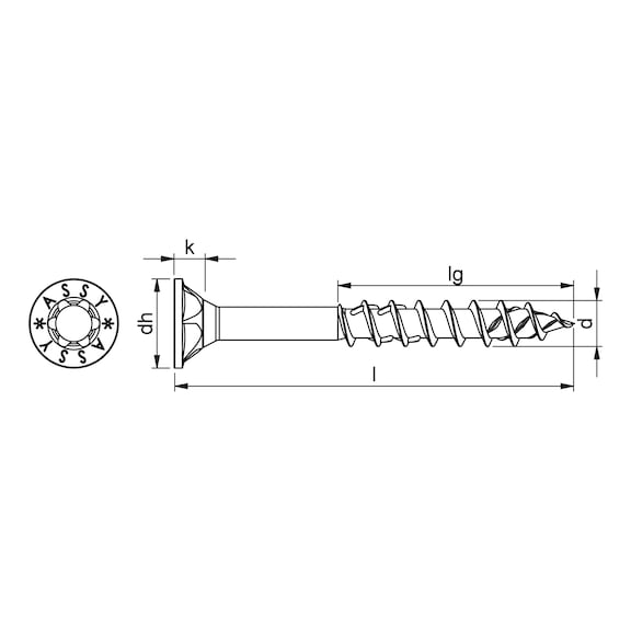
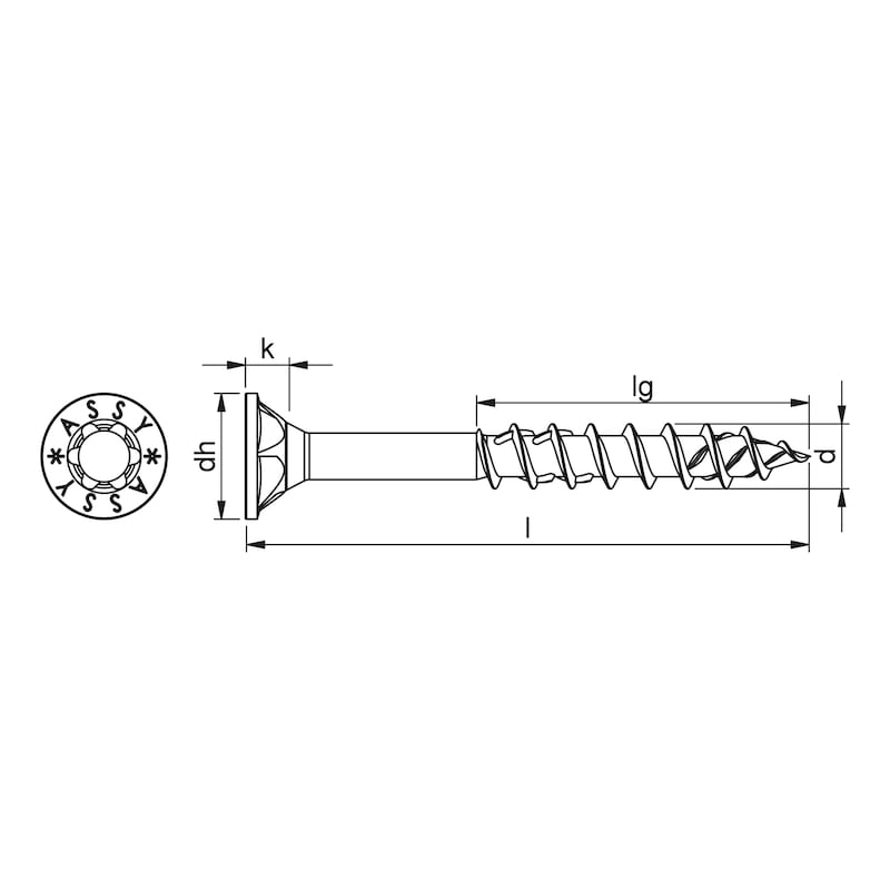
Nominal diameter (d) | 6 mm |
Length (l) | 200 mm |
Thread length (lg) | 70 mm |
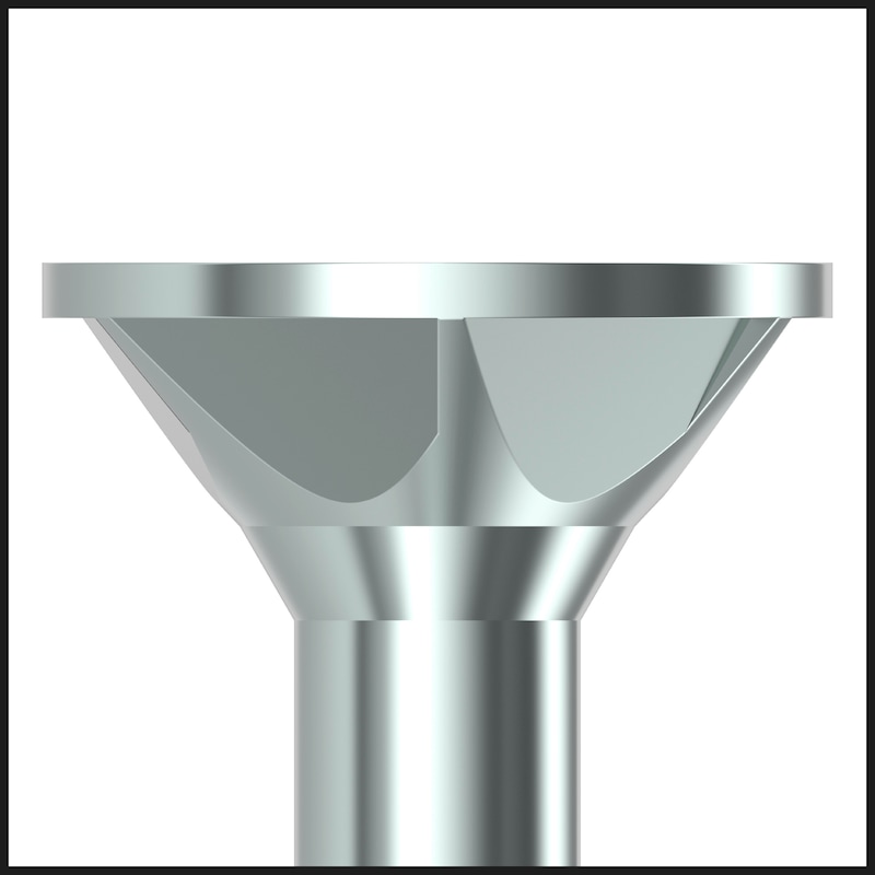
Head type | Countersunk milling pocket head |
Head details | Milling pockets |
Head diameter (dh) | 12 mm |
Head height (k) | 4.4 mm |
Internal drive | RW40 |
Thread type | Wood screw thread |
Thread design | Partial thread |
End milling cutter | Yes |
Thread form | Coarse thread |
Core diameter | 3.9 mm |
Shape of tip | Tip with hilltop milling cutter |
Angle of the tip | 34 Degree |
Material | Hardened steel |
Surface | Zinc plated |
Colour | Silver |
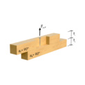
Min./max. screw-in angle | 0-90 Degree |
Suitable for use in the following materials | Wood |
Area of application | Universal |
Suitable machines | Würth BS 14-A Combi |
Screw requiring approval | Yes |
Approval | ETA-11/0190 |
RoHS-compliant | Yes |
| General information | |||
| The load capacities were determined in accordance with ETA-11/0190 (23.07.2018), DIN EN 1995-1-1:2010-12 and DIN EN 1995-1-1/NA:2013-08 for ASSY® screws without pre-drilling and a gross wood density of ρk ≥ 350 kg/m3. The load tables show a comprehensive range of options. Additional measurement options are available using the Würth Technical Software. Further information is available at www.wuerth.de/assy. | |||
| The shear load resistance values Fv,Rk in the table have been determined taking into account the "rope effect" ΔFv,Rk. In the case of simultaneous axial and lateral loads, the shear load capacities listed in the table may not be used. If proof of combined load is required, the requirement of DIN EN 1995-1-1, Gl. (8.28) applies, whereby Fv,Rk is to be considered without rope effect component. The Würth Technical Software can be used for the latter. | |||
| Product: | ASSY 4 CSMP | Screw material: | Steel, hardened |
| Art. no.: | 0190 1XX XXX | Corrosion protection: | A3K |
| Application: | Wood/wood, single shear connection | Maximum usage class: | 2 |
| Gross weight wood 1/wood 2: | 350 kg/m3/350 kg/m3 | Calculation basis: | ETA-11/0190:2018 |
| Load tables | |||
| Combined load | |||
 | Shear resistance Fv,Rk for a 90° wood/wood connection to wood fibre with required minimum screw length ℓreq |
| With washer/countersunk washer | With washer/countersunk washer | With washer/countersunk washer | ||||||||||||||
| Fv,Rk | ℓreq | Fv,Rk | ℓreq | Fv,Rk | ℓreq | Fv,Rk | ℓreq | Fv,Rk | ℓreq | Fv,Rk | ℓreq | Fv,Rk | ℓreq | Fv,Rk | ℓreq | |
| mm | kN | mm | kN | mm | kN | mm | kN | mm | kN | mm | kN | mm | kN | mm | kN | mm |
| 24 | 1,28 | 55 | 1,71 | 60 | 2,09 | 80 | 2,41 | 100 | ||||||||
| 30 | 1,43 | 70 | 1,85 | 70 | 2,23 | 80 | 2,73 | 80 | 2,59 | 100 | 3,56 | 120 | ||||
| 40 | 1,48 | 80 | 2,10 | 80 | 2,53 | 90 | 3,01 | 100 | 3,98 | 100 | 2,84 | 110 | 3,84 | 120 | 5,12 | 140 |
| 50 | 1,48 | 90 | 2,10 | 90 | 2,65 | 100 | 3,34 | 120 | 4,34 | 120 | 2,84 | 120 | 4,17 | 140 | 5,47 | 140 |
| 60 | 1,48 | 100 | 2,10 | 100 | 2,65 | 120 | 3,47 | 120 | 4,73 | 140 | 2,84 | 130 | 4,30 | 140 | 5,87 | 160 |
| 80 | 1,51 | 120 | 2,10 | 130 | 2,65 | 140 | 3,47 | 140 | 4,81 | 160 | 2,84 | 150 | 4,30 | 160 | 5,95 | 180 |
| 100 | 1,20 | 120 | 2,10 | 150 | 2,65 | 160 | 3,47 | 160 | 4,81 | 180 | 2,84 | 180 | 4,30 | 180 | 5,95 | 200 |
| 120 | 2,10 | 180 | 2,65 | 180 | 3,47 | 180 | 4,81 | 200 | 2,84 | 200 | 4,30 | 200 | 5,95 | 220 | ||
| 140 | 2,10 | 200 | 2,65 | 200 | 3,47 | 200 | 4,81 | 220 | 2,84 | 220 | 5,95 | 240 | ||||
| 160 | 2,10 | 220 | 2,65 | 220 | 3,47 | 240 | 4,81 | 240 | 2,84 | 240 | 4,30 | 240 | 5,95 | 260 | ||
| 180 | 2,10 | 240 | 2,65 | 240 | 3,47 | 260 | 4,81 | 260 | 2,84 | 260 | 4,30 | 260 | 5,95 | 280 | ||
| 200 | 2,10 | 260 | 2,65 | 260 | 3,47 | 280 | 4,81 | 280 | 2,84 | 280 | 4,30 | 280 | 5,95 | 300 | ||
| 220 | 2,10 | 280 | 2,65 | 280 | 3,47 | 300 | 4,81 | 300 | 2,84 | 300 | 4,30 | 300 | 5,95 | 320 | ||
| 240 | 2,10 | 300 | 2,65 | 300 | 3,47 | 320 | 4,81 | 320 | 2,67 | 300 | 4,30 | 320 | 5,95 | 340 | ||
| 260 | 2,10 | 300 | 2,65 | 300 | 3,47 | 340 | 4,81 | 340 | 2,32 | 300 | 4,30 | 340 | 5,95 | 360 | ||
| 280 | 3,47 | 360 | 4,81 | 360 | 4,30 | 360 | 5,95 | 380 | ||||||||
| 300 | 3,47 | 380 | 4,81 | 380 | 4,30 | 380 | 5,95 | 400 | ||||||||
| 320 | 3,47 | 400 | 4,81 | 400 | 4,30 | 400 | 5,90 | 400 | ||||||||
| t1 | ∅ 5 | ∅ 6 | ∅ 7 | ∅ 8 | ∅ 10 | ∅ 6 | ∅ 8 | ∅ 10 | ||||||||
 | Pull-out resistance Fax,Rk for a 90° wood/wood connection to wood fibre with required minimum screw length ℓreq |
| With washer/countersunk washer | With washer/countersunk washer | With washer/countersunk washer | ||||||||||||||
| Fax,Rk | ℓreq | Fax,Rk | ℓreq | Fax,Rk | ℓreq | Fax,Rk | ℓreq | Fax,Rk | ℓreq | Fax,Rk | ℓreq | Fax,Rk | ℓreq | Fax,Rk | ℓreq | |
| mm | kN | mm | kN | mm | kN | mm | kN | mm | kN | mm | kN | mm | kN | mm | kN | mm |
| 24 | 1,20 | 45 | 1,87 | 60 | 2,44 | 80 | 4,84 | 100 | ||||||||
| 30 | 1,20 | 50 | 1,87 | 60 | 2,44 | 80 | 2,93 | 80 | 4,84 | 110 | 6,25 | 120 | ||||
| 40 | 1,20 | 60 | 1,87 | 70 | 2,44 | 80 | 2,93 | 80 | 4,45 | 100 | 4,84 | 120 | 6,25 | 120 | 9,00 | 140 |
| 50 | 1,20 | 70 | 1,87 | 80 | 2,44 | 90 | 2,93 | 100 | 4,45 | 100 | 4,84 | 130 | 6,25 | 140 | 9,00 | 140 |
| 60 | 1,20 | 80 | 1,87 | 90 | 2,44 | 100 | 2,93 | 100 | 4,45 | 120 | 4,84 | 140 | 6,25 | 140 | 9,00 | 160 |
| 80 | 1,20 | 110 | 1,87 | 130 | 2,44 | 120 | 2,93 | 140 | 4,45 | 140 | 4,84 | 160 | 6,25 | 160 | 9,00 | 180 |
| 100 | 1,20 | 120 | 1,87 | 150 | 2,44 | 140 | 2,93 | 160 | 4,45 | 160 | 4,84 | 180 | 6,25 | 180 | 9,00 | 200 |
| 120 | 1,87 | 180 | 2,44 | 180 | 2,93 | 180 | 4,45 | 180 | 4,84 | 200 | 6,25 | 200 | 9,00 | 220 | ||
| 140 | 1,87 | 200 | 2,44 | 200 | 2,93 | 200 | 4,45 | 200 | 4,84 | 220 | 6,25 | 220 | 9,00 | 240 | ||
| 160 | 1,87 | 220 | 2,44 | 220 | 2,93 | 240 | 4,45 | 220 | 4,84 | 240 | 6,25 | 240 | 9,00 | 260 | ||
| 180 | 1,87 | 240 | 2,44 | 240 | 2,93 | 260 | 4,45 | 240 | 4,84 | 260 | 6,25 | 260 | 9,00 | 280 | ||
| 200 | 1,87 | 260 | 2,44 | 260 | 2,93 | 280 | 4,45 | 260 | 4,84 | 280 | 6,25 | 280 | 9,00 | 300 | ||
| 220 | 1,87 | 280 | 2,44 | 280 | 2,93 | 300 | 4,45 | 280 | 4,84 | 300 | 6,25 | 300 | 9,00 | 320 | ||
| 240 | 1,87 | 300 | 2,44 | 300 | 2,93 | 320 | 4,45 | 300 | 3,83 | 300 | 6,25 | 320 | 9,00 | 340 | ||
| 260 | 1,87 | 300 | 2,44 | 300 | 2,93 | 340 | 4,45 | 340 | 2,45 | 300 | 6,25 | 340 | 9,00 | 360 | ||
| 280 | 2,93 | 360 | 4,45 | 360 | 6,25 | 360 | 9,00 | 380 | ||||||||
| 300 | 2,93 | 380 | 4,45 | 380 | 6,25 | 380 | 9,00 | 400 | ||||||||
| 320 | 2,93 | 400 | 4,45 | 400 | 6,25 | 400 | 8,03 | 400 | ||||||||
| t1 | ∅ 5 | ∅ 6 | ∅ 7 | ∅ 8 | ∅ 10 | ∅ 6 | ∅ 8 | ∅ 10 | ||||||||
| Key | General information | ||
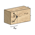
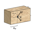
| α | Angle between screw axis and grain direction of the component | • | Carbon steel screws may be used in usage classes 1 and 2 |
| t1 | Thickness of component at head end | • | For connections with multiple screws, observe the effective number, nef, in acc. with DIN EN 1995-1-1, |
| t2 | Component 2: t2 ≥ ℓreq - t1 (observe minimum component thicknesses) | Gl. (8.17) for shear loads and in acc. with ETA-11/0190, A.2.3.2 for axial loads | |
| Fv,Rk | Characteristic resistance of a screw to shearing incl. rope effect | to be considered | |
| Fax,Rk | Characteristic resistance of a screw in the axial direction (thread pull-out, head | • | Specifications and pre-requisites in acc. with ETA-11/0190 and DIN EN 1995-1-1 to be adhered to |
| pull-through, steel failure) | • | When maintaining the minimum component thickness and minimum screw spacings in acc. with | |
| ℓreq | Required screw length to achieve load capacity | DIN EN 1995-1-1 and ETA-11/0190, pre-drilling is not necessary | |
| • | Calculations are based on ETA-11/0190 and DIN EN 1995-1-1 | ||
| • | For shear load, the measured load capacity results from Fv,Rd = Fv,Rk · kmod / γM and for | ||
| axial load, from Fax,Rd = Fax,Rk · kmod / γM | |||
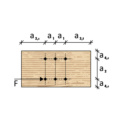
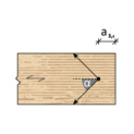
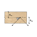
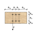
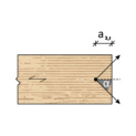
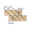
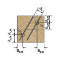
| Edge distances in wood under shear load | |||||
 |  | ||||
 |  |  | 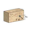 | 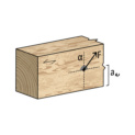 | |
| Stressed end grain -90° < α < 90° | Unstressed end grain 90° < α < 270° | Stressed edge 0° < α < 180° | Unstressed edge 180° < α < 360° | ||
| Bracket between load and grain direction α = 0° | Bracket between load and grain direction α = 90° | ||||
| Minimum spacing in mm for non-pre-drilled screws in wooden components ρk ≤ 420 kg/m3 | |||||||||||||
| 10 x d | 5 x d | 15 x d | 10 x d | 5 x d | 5 x d | 5 x d | 5 x d | 10 x d | 10 x d | 7 x d | 5 x d | ||
| 3 | 30 | 15 | 45 | 30 | 15 | 15 | 3 | 15 | 15 | 30 | 30 | 21 | 15 |
| 3,5 | 35 | 17,5 | 52,5 | 35 | 17,5 | 17,5 | 3,5 | 17,5 | 17,5 | 35 | 35 | 24,5 | 17,5 |
| 4 | 40 | 20 | 60 | 40 | 20 | 20 | 4 | 20 | 20 | 40 | 40 | 28 | 20 |
| 4,5 | 45 | 22,5 | 67,5 | 45 | 22,5 | 22,5 | 4,5 | 22,5 | 22,5 | 45 | 45 | 31,5 | 22,5 |
| 12 x d | 5 x d | 15 x d | 10 x d | 5 x d | 5 x d | 5 x d | 5 x d | 10 x d | 10 x d | 10 x d | 5 x d | ||
| 5 | 60 | 25 | 75 | 50 | 25 | 25 | 5 | 25 | 25 | 50 | 50 | 50 | 25 |
| 72 | 30 | 90 | 60 | 30 | 30 | 30 | 30 | 60 | 60 | 60 | 30 | ||
| 84 | 35 | 105 | 70 | 35 | 35 | 35 | 35 | 70 | 70 | 70 | 35 | ||
| 96 | 40 | 120 | 80 | 40 | 40 | 40 | 40 | 80 | 80 | 80 | 40 | ||
| 120 | 50 | 150 | 100 | 50 | 50 | 50 | 50 | 100 | 100 | 100 | 50 | ||
| 1) The minimum spacing is determined in accordance with DIN EN 1995-1-1 tab. 8.2 for non-pre-drilled nail holes, where d is the thread outer diameter 2) The minimum spacing between 0° < α < 90° load to the direction of the grain can be determined more precisely in accordance with DIN EN 1995-1-1 tab. 8.2 | |||||||||||||
| Bracket between load and grain direction α = 0° | Bracket between load and grain direction α = 90° | ||||||||||||
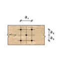
| Minimum spacing in mm for non-pre-drilled screws in wooden components 420 kg/m3 ≤ ρk ≤ 500 kg/m3 | |||||||||||||
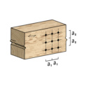
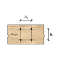
| d in mm | a1 | a2 | a3,t | a3,c | a4,t | a4,c | d in mm | a1 | a2 | a3,t | a3,c | a4,t | a4,c |
| 15 x d | 7 x d | 20 x d | 15 x d | 7 x d | 7 x d | 7 x d | 7 x d | 15 x d | 15 x d | 9 x d | 7 x d | ||
| 3 | 45 | 21 | 60 | 45 | 21 | 21 | 3 | 21 | 21 | 45 | 45 | 27 | 21 |
| 3,5 | 52,5 | 24,5 | 70 | 52,5 | 24,5 | 24,5 | 3,5 | 24,5 | 24,5 | 52,5 | 52,5 | 31,5 | 24,5 |
| 4 | 60 | 28 | 80 | 60 | 28 | 28 | 4 | 28 | 28 | 60 | 60 | 36 | 28 |
| 4,5 | 67,5 | 31,5 | 90 | 67,5 | 31,5 | 31,5 | 4,5 | 31,5 | 31,5 | 67,5 | 67,5 | 40,5 | 31,5 |
| 15 x d | 7 x d | 20 x d | 15 x d | 7 x d | 7 x d | 7 x d | 7 x d | 15 x d | 15 x d | 12 x d | 7 x d | ||
| 5 | 75 | 35 | 100 | 75 | 35 | 35 | 5 | 35 | 35 | 75 | 75 | 60 | 35 |
| 6 | 90 | 42 | 120 | 90 | 42 | 42 | 6 | 42 | 42 | 90 | 90 | 72 | 42 |
| 7 | 105 | 49 | 140 | 105 | 49 | 49 | 7 | 49 | 49 | 105 | 105 | 84 | 49 |
| 8 | 120 | 56 | 160 | 120 | 56 | 56 | 8 | 56 | 56 | 120 | 120 | 96 | 56 |
| 10 | 150 | 70 | 200 | 150 | 70 | 70 | 10 | 70 | 70 | 150 | 150 | 120 | 70 |
| 1) The minimum spacing is determined in accordance with DIN EN 1995-1-1 tab. 8.2 for non-pre-drilled nail holes, where d is the thread outer diameter 2) The minimum spacing also apply to screw diameter ≥ 5 mm in components made of BauBuche (ETA-14/0354) for component thicknesses of t ≥ 7 x d 3) The minimum spacing between 0° < α < 90° load to the direction of the grain can be determined more precisely in accordance with DIN EN 1995-1-1 tab. 8.2 4) Wooden components with ρk > 500 kg/m3 must always be pre-drilled | |||||||||||||
| Bracket between load and grain direction α = 0° | Bracket between load and grain direction α = 90° | ||||||||||||
| Minimum spacing in mm for pre-drilled screw connections in softwood, hardwood, BauBuche | |||||||||||||
| d in mm | a1 | a2 | a3,t | a3,c | a4,t | a4,c | d in mm | a1 | a2 | a3,t | a3,c | a4,t | a4,c |
| 5 x d | 3 x d | 12 x d | 7 x d | 3 x d | 3 x d | 4 x d | 4 x d | 7 x d | 7 x d | 5 x d | 3 x d | ||
| 3 | 15 | 9 | 36 | 21 | 9 | 9 | 3 | 12 | 12 | 21 | 21 | 15 | 9 |
| 3,5 | 17,5 | 10,5 | 42 | 24,5 | 10,5 | 10,5 | 3,5 | 14 | 14 | 24,5 | 24,5 | 17,5 | 10,5 |
| 4 | 20 | 12 | 48 | 28 | 12 | 12 | 4 | 16 | 16 | 28 | 28 | 20 | 12 |
| 4,5 | 22,5 | 13,5 | 54 | 31,5 | 13,5 | 13,5 | 4,5 | 18 | 18 | 31,5 | 31,5 | 22,5 | 13,5 |
| 5 x d | 3 x d | 12 x d | 7 x d | 3 x d | 3 x d | 4 x d | 4 x d | 7 x d | 7 x d | 7 x d | 3 x d | ||
| 5 | 25 | 15 | 60 | 35 | 15 | 15 | 5 | 20 | 20 | 35 | 35 | 35 | 15 |
| 6 | 30 | 18 | 72 | 42 | 18 | 18 | 6 | 24 | 24 | 42 | 42 | 42 | 18 |
| 7 | 35 | 21 | 84 | 49 | 21 | 21 | 7 | 28 | 28 | 49 | 49 | 49 | 21 |
| 8 | 40 | 24 | 96 | 56 | 24 | 24 | 8 | 32 | 32 | 56 | 56 | 56 | 24 |
| 10 | 50 | 30 | 120 | 70 | 30 | 30 | 10 | 40 | 40 | 70 | 70 | 70 | 30 |
| 1) The minimum spacing is determined in accordance with DIN EN 1995-1-1 tab. 8.2 for pre-drilled nail holes, where d is the thread outer diameter 2) The minimum spacing between 0° < α < 90° load to the direction of the grain can be determined more precisely in accordance with DIN EN 1995-1-1 tab. 8.2 | |||||||||||||
| Bracket between load and grain direction α = 0° | Bracket between load and grain direction α = 90° | ||||||||||||
| d in mm | 3 | 3,5 | 4 | 4,5 | 5 | 6 | 7 | 8 | 10 |
| Softwood | 1,5 | 2,0 | 2,5 | 2,5 | 3,0 | 4,0 | 4,0 | 5,0 | 6,0 |
| Hardwood | 2,0 | 2,5 | 3,0 | 3,5 | 3,5 | 4,0 | 5,0 | 6,0 | 7,0 |
| BauBuche1) | 2,5 | 2,5 | 3,0 | 3,5 | 4,0 | 4,5 | 5,5 | 6,5 | 8,0 |
| 1) According to 1459 expert report SWG ASSY BauBuche | |||||||||
| Pre-drilling diameter acc. to ETA-11/0190 in mm | |||||||||
| If the spacing between the screws in the direction of the grain and to the end grain is at least 25 x d, the spacing to the unstressed edge at right angles to the grain direction may be reduced to 3 x d, even with component thicknesses of t < 5 x d | |
| The minimum thicknesses of the components to be connected must be observed in accordance with ETA-11/0190 (A.2.4.2) | |
| • | When using woods at risk of splitting, the screw connections should always be pre-drilled |
| • | For steel-wood connections, the minimum spacing (a1, a2) can be multiplied by a coefficient of 0.7 |
| For wooden plate connections, the minimum spacing (a1, a2) can be multiplied by a coefficient of 0.85 | |
| • | For Douglas fir wooden components, the minimum clearances in the direction of the grain must be increased by 50 % |
| Notes | |
 | |||
 |  |  |  |
 |  |  | |
| Edge distances in cross-laminated timber under shear load | |||
| Minimum spacing in mm for screws in cross-laminated timber | |||||||||||||
| d in mm | a1 | a2 | a3,t | a3,c | a4,t | a4,c | d in mm | a1 | a2 | a3,t | a3,c | a4,t | a4,c |
| 4 x d | 2.5 x d | 6 x d | 6 x d | 6 x d | 2.5 x d | 10 x d | 4 x d | 12 x d | 7 x d | 6 x d | 3 x d | ||
| 6 | 24 | 15 | 36 | 36 | 36 | 15 | 6 | 60 | 24 | 72 | 42 | 36 | 18 |
| 7 | 28 | 17,5 | 42 | 42 | 42 | 17,5 | 7 | 70 | 28 | 84 | 49 | 42 | 21 |
| 8 | 32 | 20 | 48 | 48 | 48 | 20 | 8 | 80 | 32 | 96 | 56 | 48 | 24 |
| 10 | 40 | 25 | 60 | 60 | 60 | 25 | 10 | 100 | 40 | 120 | 70 | 60 | 30 |
| Side surfaces | Front surfaces | ||||||||||||
| • | The values apply to a minimum thickness of the component of 10 x d |
| • | The minimum embedment depth of the screws in the front surface of the cross-laminated timber is 10 x d |
| • | The requirements of the respective manufacturers of cross-laminated timber components must be similarly observed |
| Notes | |
 | |||
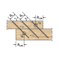 | 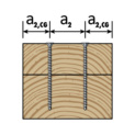 |  |  |
| Edge distances in wood with an axial load | |||
| DIN EN 1995-1-1 | a1 | a2 | a1,CG | a2,CG |
| ETA-11/0190 | a1 | a2 | a1,c | a2,c |
| d in mm | 7 x d | 5 x d | 10 x d | 4 x d |
| 3 | 21 | 15 | 30 | 12 |
| 3,5 | 24,5 | 17,5 | 35 | 14 |
| 4 | 28 | 20 | 40 | 16 |
| 4,5 | 31,5 | 22,5 | 45 | 18 |
| 5 | 35 | 25 | 50 | 20 |
| 6 | 42 | 30 | 60 | 24 |
| 7 | 49 | 35 | 70 | 28 |
| 8 | 56 | 40 | 80 | 32 |
| 10 | 70 | 50 | 100 | 40 |
| Minimum spacing in mm for screws in wooden components | ||||
| • | The minimum spacing is defined in accordance with DIN EN 1995-1-1 tab. 8.6, where d is the thread outer diameter |
| • | The minimum thicknesses of the components to be connected must be observed in accordance with ETA-11/0190 (A.2.4.3) |
| • | For combined shear and axial tensile loads, the minimum spacing for screws and shear stress must be used |
| Notes | |
Select RAL-colour code
!! NOTE: On-screen visualisation of the colour differs from real colour shade!!