


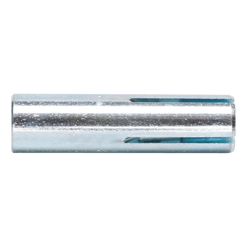


Drop-in anchor W-ED/S
Wedge anchor W-ED/S steel zinc plated
ANC-(W-ED/S)-(A2K)-M8
price per selected packing unit | Individual prices for customers after login


Register now and access more than 125,000 products
- Small drill hole depth
- High load-bearing capacities
- Visual setting check and hand protection when installing with the marking/expander tool
- Mechanical setting tool makes installation quicker and easier
- Immediate load-bearing capacity – no waiting
- Attached part can easily be removed at any time
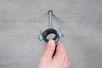
- The attached part can be anchored with a fastening screw or a threaded rod
- No installation torque required
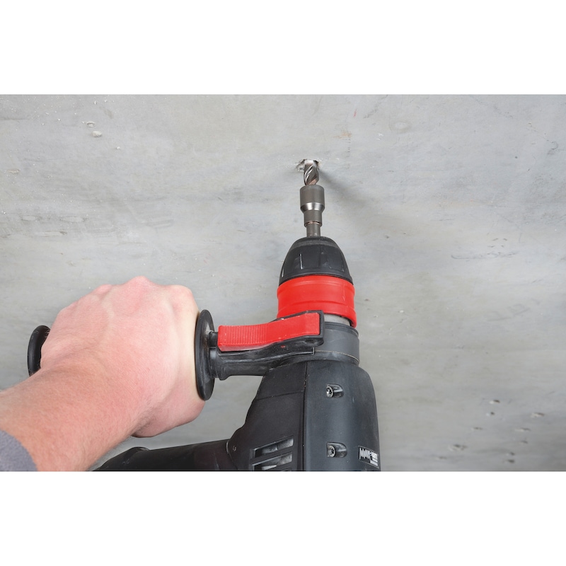
- The stop bit used with the attachable expander tool makes it quicker and easier to install. The matching drill holes make the installation even more secure.
- ETA-02/0044 for individual fixing point, option 7, uncracked concrete
- ETA-05/0120 for anchors in a redundant non-structural system, uncracked and cracked concrete, M6-M16
- Fire resistance: F30, F60, F90 and F120; exposure to fire according to DIN 4102-2:1977-09 (UTTC - uniform temperature time curve)
- Fire resistance: R30, R60, R90 and R120; TR020 (included in ETA-05/0120)
Drive-in anchor W-ED/A4 see [13.2]
Drive-in anchor W-ED, M12 (for core drills), and W-ED, DW15, see [13.3]


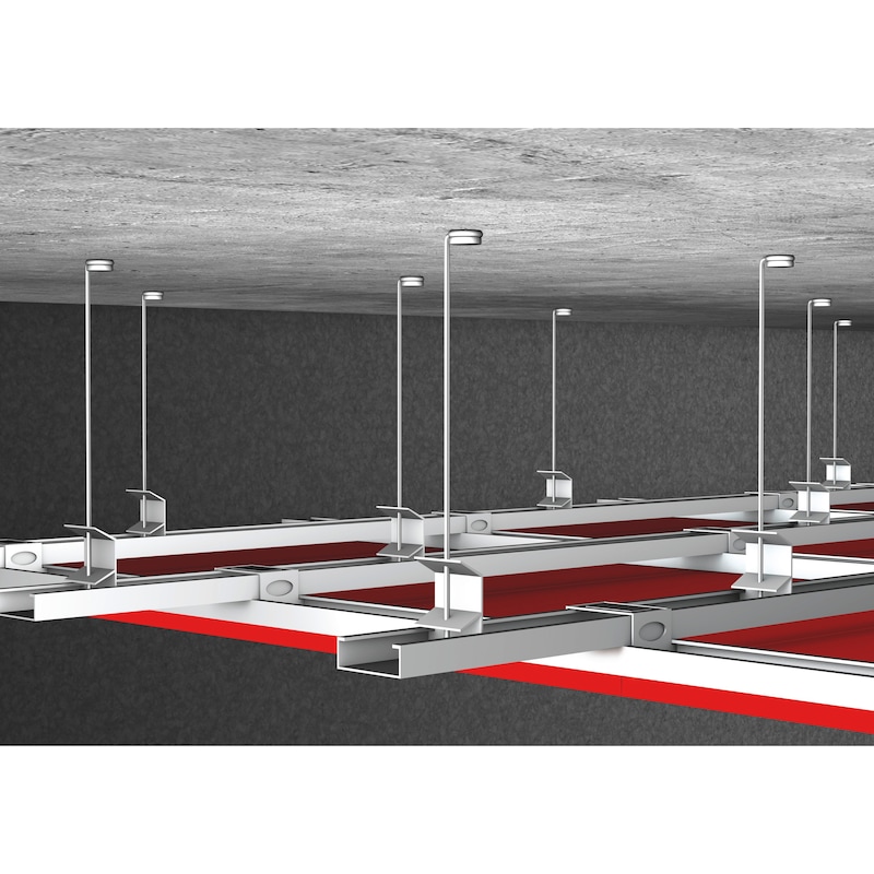
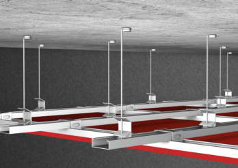 Suspended ceilings
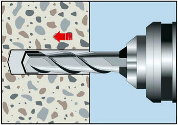
Drill hole
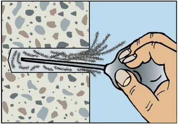
Clean the drill hole
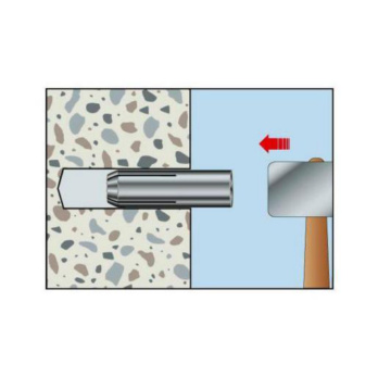
Knock in anchor until flush
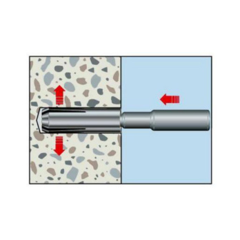
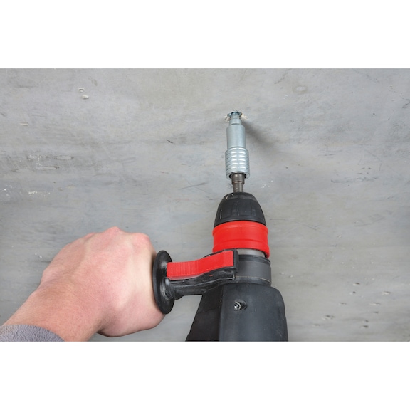
Anchor with expander tool
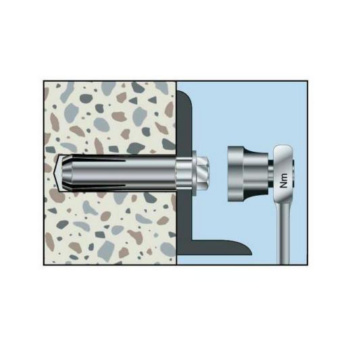
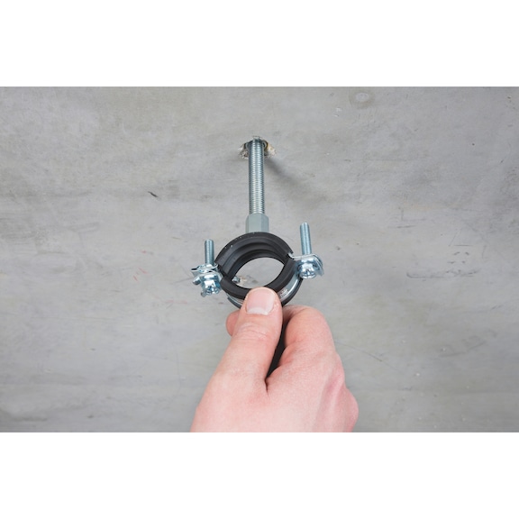
Fit component, apply torque
- ETA-02/0044 for individual fixing point, option 7, uncracked concrete
- ETA-05/0120 for anchors in a redundant non-structural system, uncracked and cracked concrete, M6-M16
- Fire resistance: F30, F60, F90 and F120; exposure to fire according to DIN 4102-2:1977-09 (UTTC - uniform temperature time curve)
- Fire resistance: R30, R60, R90 and R120; TR020 (included in ETA-05/0120)
Datasheets(X)

Individual fixing point: Normal weight concrete C20/25 to C50/60 (uncracked concrete)
Anchors in a redundant non-structural system: Anchorage of non-load-bearing systems (M6-M16, cracked and uncracked concrete)
E.g. threaded rods, metal structures, metal profiles, lattices, cable conduits, pipes, mounting rails etc.
For use in concrete < C20/25 and pressure-resistant natural stone (without approval)
May only be used in dry indoor conditions
Anchor diameter | 8 mm |
Anchor length (L H) | 30 mm |
Min./max. required screw-in depth | 9-13 mm |
Material | Steel |
Surface | Zinc plated |
Nominal drill-bit diameter (d 0) | 10 mm |
Drill hole depth (h 0) | 30 mm |
Effective anchoring depth (h ef) | 30 mm |
Torque during anchoring (T inst) | 8 Nm |
Through-hole in the component to be connected (d f) | 9 mm |
Approval | ETA-02/0044 |
| Performance data (screw 5.6-8.8) | |||||||
| Anchor diameter [mm] | M58) | M68) | M8 x 308) | M8 x 40 | M10 x 308) | ||
| Admissible centric tension load1) on an individual anchor without the influence of the edge distance | Compressive zone (uncracked concrete C20/252), s ≥ 3 hef, c ≥ cmin) | Nadm [kN] = C20/252) | Frec 1.4 | 3,3 | 3,3 | 3,6 | 3,3 |
| Admissible shear load1) on an individual anchor without the influence of the edge distance | Compressive zone (uncracked concrete C20/252), c ≥ 10 hef) | Vadm [kN] = C20/25 2) 3) | Frec 1.5 | 2,1 | 3,9 | 3,9 | 4,0 |
| Anchors in a redundant non-structural system in concrete4) | Fadm [kN] ≥ C20/25 | 1,2 | 1.79) | 2.09) | 2.09) | ||
| Admissible bending moment 5) uncracked concrete/anchors in a redundant non-structural system | Madm [Nm] | - | 3.3/ 3.3 | 8.1/ 8.1 | 15.8/ 15.8 | ||
| Admissible load when exposed to fire 4) (Technical Report TR 020) For axis and edge distances, see European Technical Approval ETA-05/0120 | R30; Fadm [kN] | - | 0,8 | 0,9 | 1,5 | 0,9 | |
| R60; Fadm [kN] | - | 0,8 | 0,9 | 1,5 | 0,9 | ||
| R90; Fadm [kN] | - | 0,4 | 0,9 | 0,9 | 0,9 | ||
| R120; Fadm [kN] | - | 0,3 | 0,5 | 0,5 | 0,7 | ||
| Fire resistance rating6) according to UTTC (uniform temperature time curve) | F30 [kN] | - | 1,7 | 1,7 | 3,0 | - | |
| F60 [kN] | - | 0,7 | 0,7 | 1,5 | - | ||
| F90 [kN] | - | 0,4 | 0,4 | 0,8 | - | ||
| F120 [kN] | - | 0,3 | 0,3 | 0,6 | - | ||
| 1) The partial safety factors of the resistances regulated in the approval and a partial safety factor of the actions of γF = 1.4 have been taken into account. For information on combining tensile and shear loads, on the influence of the edge distance, and on anchor groups, please refer to the European Technical Approval Guidelines (ETAG), Annex C. 2) The concrete has normal reinforcement. Higher values are possible for higher concrete compressive strengths. 3) Steel quality 5.6. With a higher steel quality, higher shear load values apply. 4) The admissible loads have been determined without the influence of the axis and edge distances and apply to screws with steel quality ≥ 5.6. 5) Steel quality 5.6. With a higher steel quality, higher admissible bending moments apply. 6) Fire resistance rating: Drop-in anchor W-ED/S in conjunction with screws of strength classes ≥ 5.6. 7) Without approval. 8) Only for use in statically indeterminate systems and dry indoor areas. 9) Number of attachment points ≥ 3 and at least 1 anchor per attachment point results in a load per attachment point of Fadm ≤ 1.4 kN or number of attachment points ≥ 4 and at least 1 anchor per attachment point results in a load per attachment point of Fadm ≤ 2.1 kN. The admissible loads can be increased if the design shows that the requirements governing the strength and rigidity of the component to be attached remain satisfied even after the failure of an anchor in terms of the limit state of serviceability and load-bearing capacity. | |||||||
| Performance data (screw 5.6-8.8) | ||||||
| Anchor diameter [mm] | M10 x 40 | M12 | M16 | M20 | ||
| Admissible centric tension load1) on an individual anchor without the influence of the edge distance | Compressive zone (uncracked concrete C20/252), s ≥ 3 hef, c ≥ cmin) | Nadm [kN] = C20/252) | 5,1 | 7,1 | 10,5 | 14,3 |
| Admissible shear load1) on an individual anchor without the influence of the edge distance | Compressive zone (uncracked concrete C20/252), c ≥ 10 hef) | Vadm [kN] = C20/25 2) 3) | 4,1 | 9,0 | 16,8 | 26,2 |
| Anchors in a redundant non-structural system in concrete4) | Fadm [kN] ≥ C20/25 | 2.09) | 2.49) | 6.39) | - | |
| Admissible bending moment 5) uncracked concrete/anchors in a redundant non-structural system | Madm [Nm] | 27.8/ 27.8 | 71.0 71.0 | 138,6 | ||
| Admissible load when exposed to fire 4) (Technical Report TR 020) For axis and edge distances, see European Technical Approval ETA-05/0120 | R30; Fadm [kN] | 1,5 | 1,5 | 4,0 | - | |
| R60; Fadm [kN] | 1,5 | 1,5 | 4,0 | - | ||
| R90; Fadm [kN] | 1,5 | 1,5 | 3,7 | - | ||
| R120; Fadm [kN] | 1,0 | 1,2 | 2,4 | - | ||
| Fire resistance rating6) according to UTTC (uniform temperature time curve) | F30 [kN] | 4,7 | 6,9 | 12,5 | 18,0 | |
| F60 [kN] | 2,4 | 3,5 | 5,6 | 8,5 | ||
| F90 [kN] | 1,3 | 1,8 | 3,5 | 5,5 | ||
| F120 [kN] | 1,0 | 1,4 | 2,5 | 4,4 | ||
| 1) The partial safety factors of the resistances regulated in the approval and a partial safety factor of the actions of γF = 1.4 have been taken into account. For information on combining tensile and shear loads, on the influence of the edge distance, and on anchor groups, please refer to the European Technical Approval Guidelines (ETAG), Annex C. 2) The concrete has normal reinforcement. Higher values are possible for higher concrete compressive strengths. 3) Steel quality 5.6. With a higher steel quality, higher shear load values apply. 4) The admissible loads have been determined without the influence of the axis and edge distances and apply to screws with steel quality ≥ 5.6. 5) Steel quality 5.6. With a higher steel quality, higher admissible bending moments apply. 6) Fire resistance rating: Drop-in anchor W-ED/S in conjunction with screws of strength classes ≥ 5.6. 7) Without approval. 8) Only for use in statically indeterminate systems and dry indoor areas. 9) Number of attachment points ≥ 3 and at least 1 anchor per attachment point results in a load per attachment point of Fadm ≤ 1.4 kN or number of attachment points ≥ 4 and at least 1 anchor per attachment point results in a load per attachment point of Fadm ≤ 2.1 kN. The admissible loads can be increased if the design shows that the requirements governing the strength and rigidity of the component to be attached remain satisfied even after the failure of an anchor in terms of the limit state of serviceability and load-bearing capacity. | ||||||
| Installation parameters | ||||||||||
| M57) | M6 | M8 x 30 | M8 x 40 | M10 x 30 | M10 x 40 | M12 | M16 | M20 | ||
| Minimum axis distance | smin [mm] | 60 | 55 | 60 | 80 | 100 | 100 | 120 | 150 | 160 |
| Minimum edge distance | cmin [mm] | 95 | 95 | 95 | 95 | 115 | 135 | 165 | 200 | 260 |
| Minimum member thickness | hmin [mm] | 100 | 100 | 100 | 100 | 120 | 120 | 130 | 160 | 200 |
| Effective anchorage depth | hef [mm] | 25 | 30 | 30 | 40 | 30 | 40 | 50 | 65 | 80 |
| Nominal drill ∅ | d0 [mm] | 8 | 8 | 10 | 10 | 12 | 12 | 15 | 20 | 25 |
| Drill cutting ∅ | dcut ≤ [mm] | 8,45 | 8,45 | 10,45 | 10,45 | 12,5 | 12,5 | 15,5 | 20,55 | 25,55 |
| Drill hole depth | h0 = [mm] | 25 | 30 | 30 | 40 | 30 | 40 | 50 | 65 | 80 |
| Through hole in the component being connected | df ≤ [mm] | 6 | 7 | 9 | 9 | 12 | 12 | 14 | 18 | 22 |
| Thread depth (max. length of thread engagement) | Lth [mm] | 10 | 13 | 13 | 20 | 12 | 15 | 18 | 23 | 34 |
| Minimum length of thread engagement | Lsdmin ≤ [mm] | 6 | 7 | 9 | 9 | 10 | 11 | 13 | 18 | 22 |
| Torque while installing anchor | Tinst ≤ [mm] | 3 | 4 | 8 | 8 | 15 | 15 | 35 | 60 | 120 |
| Installation parameters in concrete | |||||||
| Anchor size [mm] | M5x251) | M6x25 | M6x30 | M8x25 | M8x30 | M8x40 | |
| Standard component thickness | hmin,2 [mm] | 100 | 100 | 100 | 100 | 100 | 100 |
| Characteristic axis distance of uncracked concrete/anchors in a redundant non-structural system | scr,N/scr | 75/– | –/75 | 90/130 | –/75 | 90/80 | 120/210 |
| Characteristic edge distance of uncracked concrete/anchors in a redundant non-structural system | ccr,N/ccr | 3)/– | –/3) | 3)/3) | –/3) | 3)/3) | 3)/105 |
| Minimum axis distance | smin [mm] | 60 | 30 | 55 | 50 | 60 | 80 |
| Minimum edge distance | cmin [mm] | 95 | 60 | 95 | 100 | 95 | 95 |
| Minimum member thickness | hmin,1 [mm] | - | 80 | - | 80 | - | - |
| Minimum axis distance | smin [mm] | - | 30 | - | 70 | - | - |
| Minimum edge distance | cmin [mm] | - | 60 | - | 100 | - | - |
| Effective anchorage depth | hef [mm] | 25 | 25 | 30 | 25 | 30 | 40 |
| Nominal drill ∅ | d0 [mm] | 8 | 8 | 8 | 10 | 10 | 10 |
| Drill cutting ∅ | dcut ≤ [mm] | 8,45 | 8,45 | 8,45 | 10,45 | 10,45 | 10,45 |
| Drill hole depth | h0 = [mm] | 25 | 25 | 30 | 25 | 30 | 40 |
| Through hole in the component being connected | df ≤ [mm] | 6 | 7 | 7 | 9 | 9 | 9 |
| Thread depth (max. length of thread engagement) | Lth [mm] | 10 | 12 | 13 | 12 | 13 | 20 |
| Minimum length of thread engagement | Lsdmin ≤ [mm] | 6 | 6 | 7 | 8 | 9 | 9 |
| Torque while installing anchor | Tinst ≤ [Nm] | 3 | 4 | 4 | 8 | 8 | 8 |
| 1) Without approval 2) Drill hole must not cut into hollow cavities 3) Not relevant, as the minimum value is higher. | |||||||
| Installation parameters in concrete | ||||||||
| Anchor size [mm] | M10x25 | M10x30 | M10x40 | M12x25 | M12x50 | M16x65 | M20x80 | |
| Standard component thickness | hmin,2 [mm] | 100 | 120 | 120 | 100 | 130 | 160 | 200 |
| Characteristic axis distance of uncracked concrete/anchors in a redundant non-structural system | scr,N/scr | –/75 | 3)/230 | 120/170 | –/– | 150/170 | 195/400 | 240/– |
| Characteristic edge distance of uncracked concrete/anchors in a redundant non-structural system | ccr,N/ccr | –/3) | 3)/115 | 3)/3) | –/3) | 3)/3) | 3)/200 | 3)/– |
| Minimum axis distance | smin [mm] | 60 | 100 | 100 | 100 | 120 | 150 | 160 |
| Minimum edge distance | cmin [mm] | 100 | 115 | 135 | 110 | 165 | 200 | 260 |
| Minimum member thickness | hmin,1 [mm] | 80 | - | - | 80 | - | - | - |
| Minimum axis distance | smin [mm] | 70 | - | - | 100 | - | - | - |
| Minimum edge distance | cmin [mm] | 100 | - | - | 130 | - | - | - |
| Effective anchorage depth | hef [mm] | 25 | 30 | 40 | 25 | 50 | 65 | 80 |
| Nominal drill ∅ | d0 [mm] | 12 | 12 | 12 | 15 | 15 | 20 | 25 |
| Drill cutting ∅ | dcut ≤ [mm] | 12,5 | 12,5 | 12,5 | 15,5 | 15,5 | 20,55 | 25,55 |
| Drill hole depth | h0 = [mm] | 25 | 30 | 40 | 25 | 50 | 65 | 80 |
| Through hole in the component being connected | df ≤ [mm] | 12 | 12 | 12 | 14 | 14 | 18 | 22 |
| Thread depth (max. length of thread engagement) | Lth [mm] | 12 | 12 | 15 | 12 | 18 | 23 | 34 |
| Minimum length of thread engagement | Lsdmin ≤ [mm] | 10 | 10 | 11 | 12 | 13 | 18 | 22 |
| Torque while installing anchor | Tinst ≤ [Nm] | 15 | 15 | 15 | 35 | 35 | 60 | 120 |
| 1) Without approval 2) Drill hole must not cut into hollow cavities 3) Not relevant, as the minimum value is higher. | ||||||||
| Performance data in uncracked concrete - individual fixing point (screw 4.6-8.8) | |||||||
| Anchor size [mm] | M5x251)6) | M6x306) | M8x306) | M8x40 | M10x306) | ||
| Admissible centric tension load3) on an individual anchor without the influence of the edge distance | Compressive zone (uncracked concrete C20/254), s ≥ 3 hef, c ≥ cmin) | Nadm [kN] = C20/244) | Frec 1.4 | 3,3 | 3,3 | 3,6 | 3,3 |
| Admissible shear load3) on an individual anchor without the influence of the edge distance | Compressive zone (uncracked concrete C20/254), s ≥ 3 hef, c ≥ cmin) | Vadm [kN] = C20/244)5) | Frec 1.5 | 2,1 | 3,9 | 3,9 | 4,0 |
| Admissible bending moment7) | Madm [Nm] | - | 3,3 | 8,1 | 15,8 | ||
| Fire resistance8) according to UTTC (uniform temperature time curve) | F30 [kN] | - | 1,7 | 1,7 | 3,0 | - | |
| F60 [kN] | - | 0,7 | 0,7 | 1,5 | - | ||
| F90 [kN] | - | 0,4 | 0,4 | 0,8 | - | ||
| F120 [kN] | - | 0,3 | 0,3 | 0,6 | - | ||
| Performance data in uncracked concrete - individual fixing point (screw 4.6-8.8) | ||||||
| Anchor size [mm] | M10x40 | M12x50 | M16x65 | M20x80 | ||
| Admissible centric tension load3) on an individual anchor without the influence of the edge distance | Compressive zone (uncracked concrete C20/254), s ≥ 3 hef, c ≥ cmin) | Nadm [kN] = C20/244) | 5,1 | 7,1 | 10,5 | 14,3 |
| Admissible shear load3) on an individual anchor without the influence of the edge distance | Compressive zone (uncracked concrete C20/254), s ≥ 3 hef, c ≥ cmin) | Vadm [kN] = C20/244)5) | 4,1 | 9,0 | 16,8 | 26,2 |
| Admissible bending moment7) | Madm [Nm] | 27,8 | 71,0 | 138,6 | ||
| Fire resistance8) according to UTTC (uniform temperature time curve) | F30 [kN] | 4,7 | 6,9 | 12,5 | 18,0 | |
| F60 [kN] | 2,4 | 3,5 | 5,6 | 8,5 | ||
| F90 [kN] | 1,3 | 1,8 | 3,5 | 5,5 | ||
| F120 [kN] | 1,0 | 1,4 | 2,5 | 4,4 | ||
| Performance data in cracked and uncracked concrete - anchors in a redundant non-structural system (screw 4.6-8.8) | ||||||
| Anchor size [mm] | M6x25 | M6x30 | M8x25 | M8x30 | M8x40 | |
| Anchors in a redundant non-structural system in concrete10) | Fadm [kN] = C12/15 - C16/204) | 1,2 | - | 1,2 | - | - |
| Fadm [kN] = C20/25 - C50/604) | 1.79) | 1,2 | 1.99) | 1.79) | 2.09) | |
| Admissible bending moment7) | Madm [Nm] | 3,3 | 8,1 | |||
| Admissible load when exposed to fire10) | R30 [kN] | 0,4 | 0,8 | 0,6 | 0,9 | 1,5 |
| R60 [kN] | 0,4 | 0,8 | 0,6 | 0,9 | 1,5 | |
| R90 [kN] | 0,3 | 0,4 | 0,6 | 0,9 | 0,9 | |
| R120 [kN] | 0,3 | 0,3 | 0,5 | 0,5 | 0,5 | |
| Performance data in cracked and uncracked concrete - anchors in a redundant non-structural system (screw 4.6-8.8) | |||||||
| Anchor size [mm] | M10x25 | M10x30 | M10x40 | M12x25 | M12x50 | M16x65 | |
| Anchors in a redundant non-structural system in concrete10) | Fadm [kN] = C12/15 - C16/204) | 1.79) | - | - | 1.79) | - | - |
| Fadm [kN] = C20/25 - C50/604) | 2.19) | 2.09) | 2.09) | 2.19) | 2.49) | 6.39) | |
| Admissible bending moment7) | Madm [Nm] | 15,8 | 27,8 | 71,0 | |||
| Admissible load when exposed to fire10) | R30 [kN] | 0,6 | 0,9 | 1,5 | 0,6 | 1,5 | 4 |
| R60 [kN] | 0,6 | 0,9 | 1,5 | 0,6 | 1,5 | 4 | |
| R90 [kN] | 0,6 | 0,9 | 1,5 | 0,6 | 1,5 | 3,7 | |
| R120 [kN] | 0,5 | 0,7 | 1,0 | 0,5 | 1,2 | 2,4 | |
Select RAL-colour code
!! NOTE: On-screen visualisation of the colour differs from real colour shade!!